
Single Span Portal Frame | DWG.File/AutoCAD File
Category:Single Span Trusses
(0)
25.95 USD
(0 times Download )
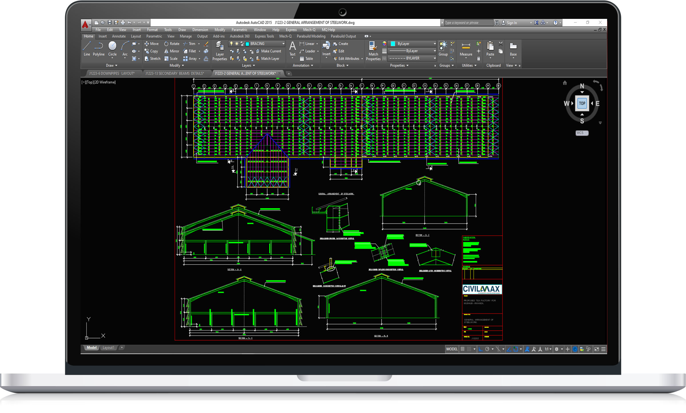
Single Span Portal Frame | DWG.File/AutoCAD File
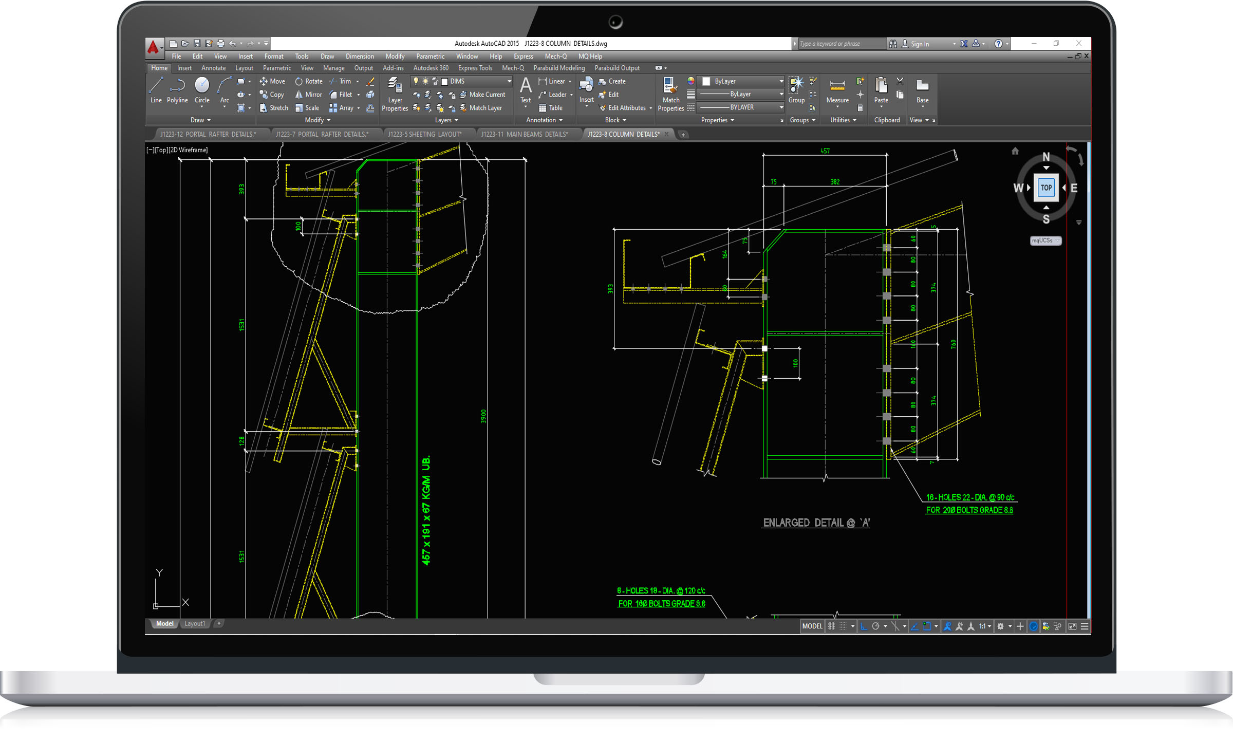
Restraint to the inner flanges of rafters or columns is often most conveniently formed by diagonal struts from the purlin or sheeting rails to small plates welded to the inner flange and web. Pressed steel flat ties are commonly used. Where restraint is only possible from one side, the restraint must be able to carry compression. In these locations angle sections of minimum size 40 × 40 mm must be used. The stay and its connections should be designed to resist a force equal to 2.5% of the maximum force in the column or rafter compression flange between adjacent restraints.
The major connections in a portal frame are the eaves and apex connections, which are both moment-resisting. The eaves connection in particular must generally carry a very large bending moment. Both the eaves and apex connection are likely to experience reversal in certain combinations of actions and this can be an important design case. For economy, connections should be arranged to minimise any requirement for additional reinforcement (commonly called stiffeners).This is generally achieved by:
- Making the haunch deeper (increasing the lever arms)
- Extending the eaves connection above the top flange of the rafter (an additional bolt row)
- Adding bolt rows
- Selecting a stronger column section.
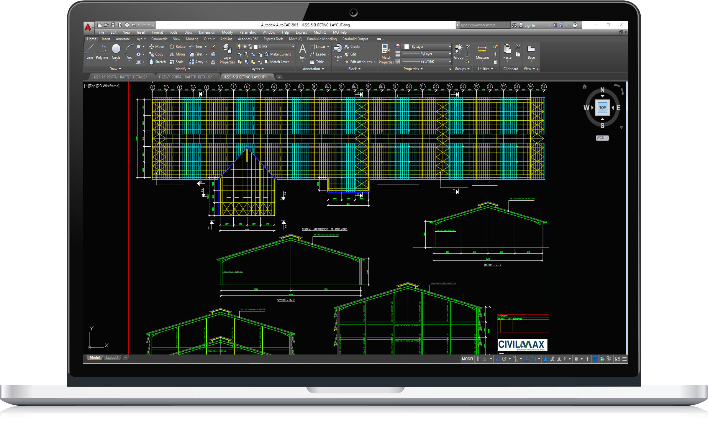
This structure have the following features:
Building floor plan dimensions: 31.00m x 174.00m long.
Column eave heights:15.00m,7.00mm
Mezzanine floor height:3.00m
This is a dwg file, it contain full sets of drawings comprising of general arrangement, assembly and single part drawings and a complete packing/material list ready for fabrication and site erection. It is an economic overhead crane building design, ideal for industrial services. All the drawings are in DWG/AutoCAD Format.