
Single Span Portal Frame | DWG.File/AutoCAD File
Category:Single Span Trusses
(0)
28.95 USD
(0 times Download )
Single Span Portal Frame | DWG.File/AutoCAD File
Having recognised any building specific requirements, decided on the most appropriate number of floors and, in general terms, how the frame will be stabilised against horizontal loading, the designer should start to consider in more detail how the frame will be laid out. The structural grid is defined principally by a regular spacing of columns, with the primary beams spanning between columns, secondary beams spanning between the primary beams, and floor slabs spanning between the secondary beams. Wherever possible the beams are laid out in an orthogonal arrangement to provide rectangular floor plates as this arrangement enables simple orthogonal connection details between beams and columns to be adopted.
Once the grids are established it is possible to estimate preliminary sizes of the beams using some rules of thumb for span to depth ratios.An estimation of the preliminary sizes of the beams using some rules of thumb for span to depth ratios for the floor systems mentioned above is presented in the table.
| Non-composite primary beams | Floor = span/20 Roof = span/25 |
| Non-composite secondary beams | Floor = span/25 Roof = span/30 |
| Composite beams | Span/16 to span/18 (note depth is steel beam plus slab) Long span solutions tend to be shallower, |
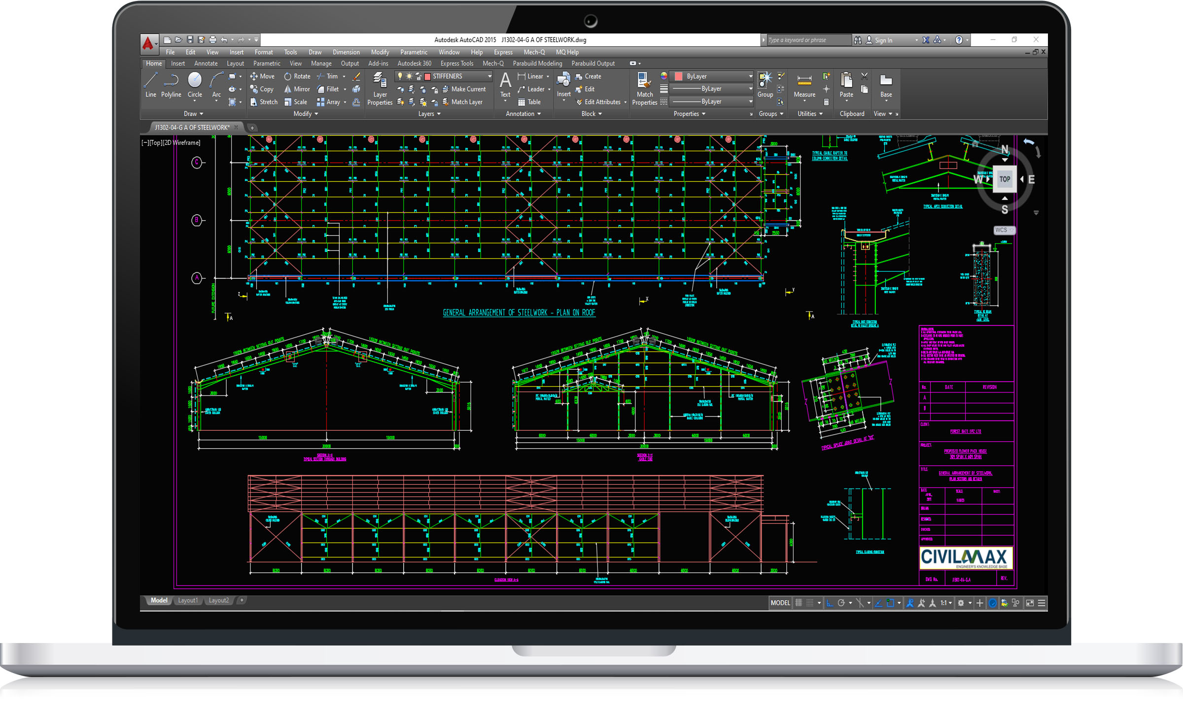
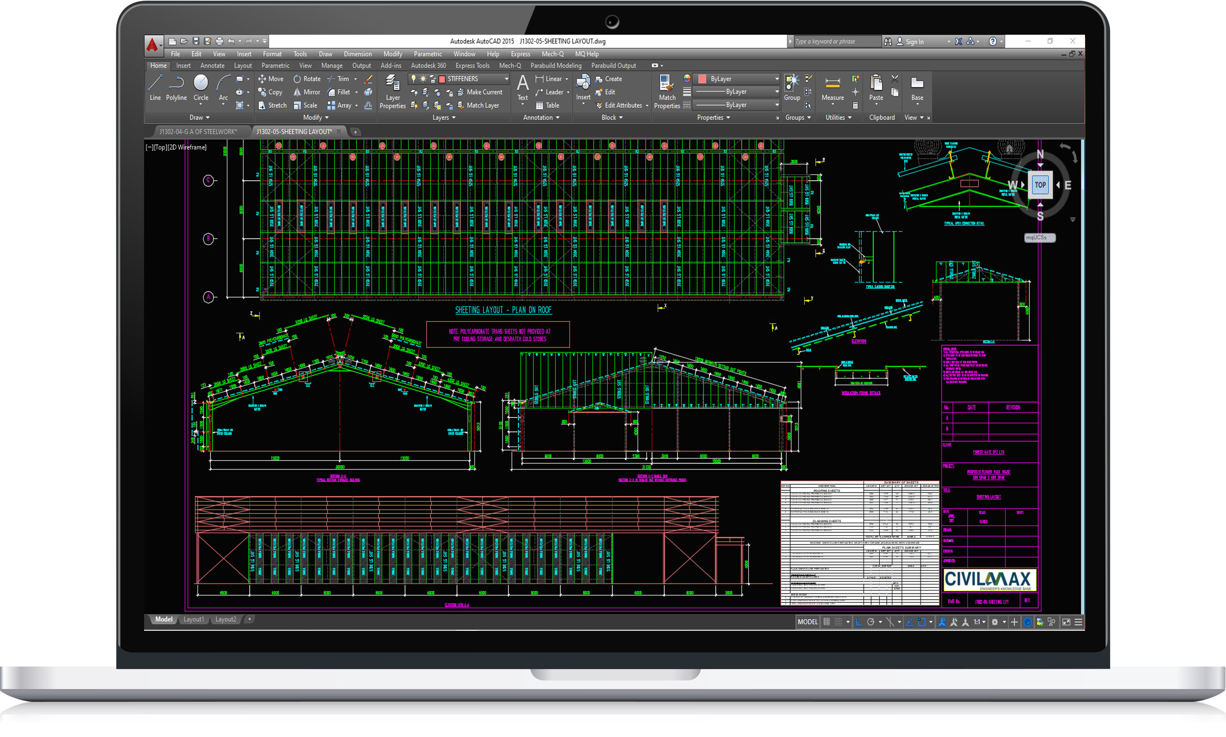
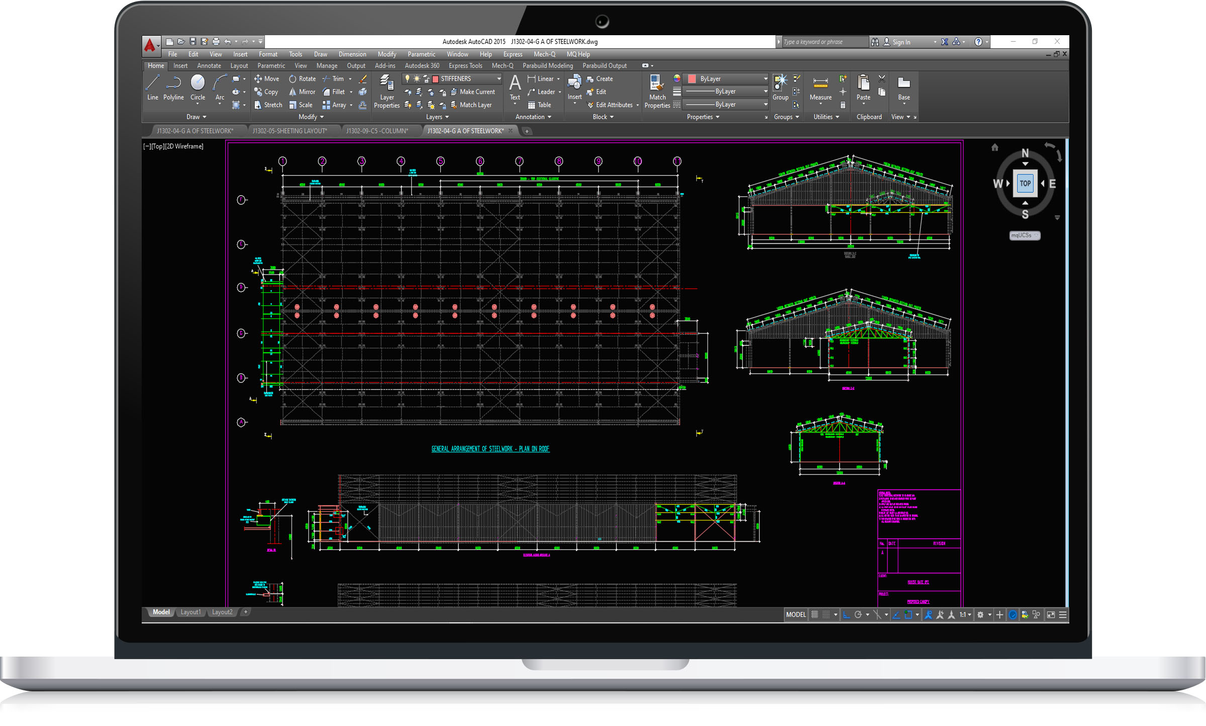
This structure have the following features:
Building floor plan dimensions: 30.00m x 60.00m long.
Column eave heights: 5.00m
This is a dwg file, it contain full sets of drawings comprising of general arrangement, assembly and single part drawings and a complete packing/material list ready for fabrication and site erection. It is an economic overhead crane building design, ideal for industrial services. All the drawings are in DWG/AutoCAD Format.